Copernicus Trajectory Design and Optimization System

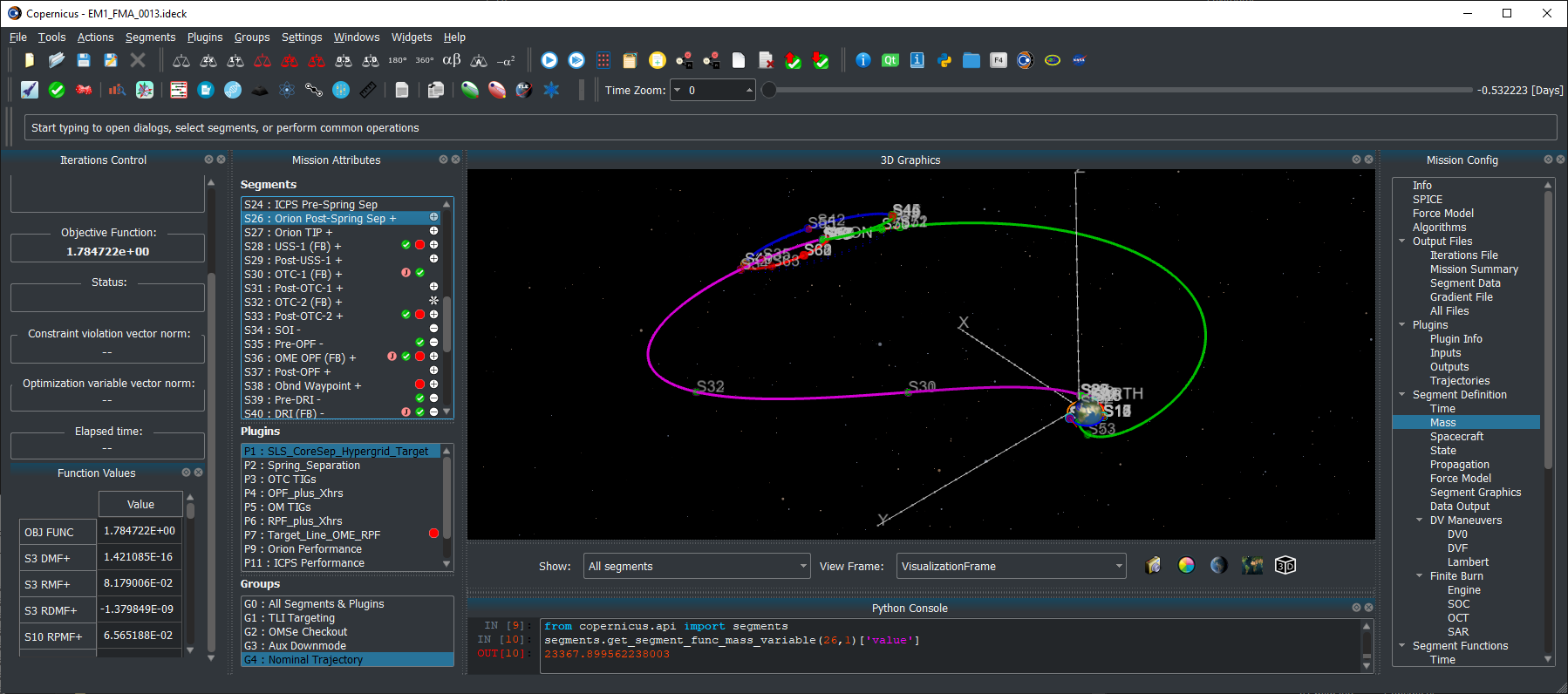
Screenshot of Copernicus with the Artemis I trajectory
NASA/JSC

Copernicus, a generalized spacecraft trajectory design and optimization system, is capable of solving a wide range of trajectory problems such as planet or moon centered trajectories, libration point trajectories, planet-moon transfers and tours, and all types of interplanetary and asteroid/comet missions.

Latest News

  • August 21, 2026: Copernicus Version 5.4.2 is now available. This is a bugfix release.
  • May 26, 2026: Copernicus Version 5.4.1 is now available. This is a bugfix release with a few new features.
  • March 23, 2026: Copernicus Version 5.4 is now available. This update includes numerous new features, enhancements, and bug fixes. This is also the first release with native support for Macs with Apple Silicon processors. Other updates include: New altitude and eclipse ramping/buffer engine model options; New propagation model to simulate a finite burn segment with a series of Kepler arcs & impulses; New circular restricted three-body problem (CR3BP) parameterization and propagation mode; New shadowing/eclipse model upgrades; New two-body rotating frame definition options; Many new GUI enhancements, usability upgrades, & improvements; Many enhancements and upgrades to the Copernicus Python API.
  • August 13, 2024: Copernicus Version 5.3.2 is now available.
  • December 18, 2023: Copernicus Version 5.3.1 is now available. This is a bugfix release.
  • November 15, 2023: Copernicus Version 5.3 is now available. This update includes many bug fixes and various new features and refinements. Including: a new Copernicus mission file format, updates to kernels, a significant expansion of the beta Python API, and various new integration methods. In addition, we have upgraded to Python 3.10, and all dependencies are now obtained via conda.
  • January 21, 2022: Copernicus Version 5.2 is now available. This update includes many bug fixes and various new features and refinements.
  • June 17, 2021: Copernicus was selected as winner of the 2021 NASA Software of the Year Award.
  • March 4, 2021: Copernicus Version 5.1 is now available. This update includes many bug fixes and various new features and refinements.
  • June 26, 2020: Copernicus Version 5.0 is now available. This is a significant update to Copernicus and includes: A new modern Python-based GUI that is now cross-platform and fully functional on Windows, Linux, and macOS, 3D graphics upgrades including antialiasing and celestial body shadowing, a new Python scripting interface, many other new features and options, and bug fixes.
  • May 1, 2018: Copernicus Version 4.6 is now available. The release includes the following changes: a new cross-platform JSON kernel file format, various new reference frame features, including new capabilities for user-defined reference frame plugins, and numerous bug fixes and other minor enhancements.
  • January 24, 2018: Copernicus Version 4.5 is now available. The new version includes a new experimental Mac version, faster exporting of segment data output files (including the addition of a new binary HDF5 format), some new GUI tools, new plugin capabilities, and numerous other new features and bug fixes.
  • October 1, 2016: Copernicus Version 4.4 is now available. The new version includes 3D graphics improvements and various other new features and bug fixes.
  • February 8, 2016: Copernicus Version 4.3 is now available. The new version includes updates to the plugin interface, a new differential corrector solution method, updated SPICE SPK files, updates to the Python interface, new training videos, as well as numerous other refinements and bug fixes.
  • July 21, 2015: Copernicus Version 4.2 is now available.  The update includes further refinements to the new plugin feature, as well as various other new features and some bug fixes.
  • April 13, 2015: Copernicus Version 4.1 is now available.  This update includes a new plugin architecture to enable extending Copernicus with user-created algorithms.  It also includes a new Python interface, as well as various other new features and bug fixes.
  • August 13, 2014: Copernicus Version 4.0 is now available.  This is an update to version 3.1, which was released in June 2012.  The new release includes many new features, bug fixes, performance and stability improvements, as well as a redesigned GUI, a new user guide, and full compatibility with Windows 7.  The update is recommended for all Copernicus users.

Development

The Copernicus Project started at the University of Texas at Austin in August 2001. In June 2002, a grant from the NASA Johnson Space Center (JSC) was used to develop the first prototype which was completed in August 2004. In the interim, support was also received from NASA’s In Space Propulsion Program and from the Flight Dynamics Vehicle Branch of Goddard Spaceflight Center. The first operational version was completed in March 2006 (v1.0). The initial development team consisted of Dr. Cesar Ocampo and graduate students at the University of Texas at Austin Department of Aerospace Engineering and Engineering Mechanics. Since March 2007, primary development of Copernicus has been at the Flight Mechanics and Trajectory Design Branch of JSC.

Request Copernicus

The National Aeronautics and Space Act of 1958 and a series of subsequent legislation recognized transfer of federally owned or originated technology to be a national priority and the mission of each Federal agency. The legislation specifically mandates that each Federal agency have a formal technology transfer program, and take an active role in transferring technology to the private sector and state and local governments for the purposes of commercial and other application of the technology for the national benefit. In accordance with NASA’s obligations under mandating legislation, JSC makes Copernicus available free of charge to other NASA centers, government contractors, and universities, under the terms of a US government purpose license.  Organizations interested in obtaining Copernicus should click here to request it.

Current Version

The current version of Copernicus is 5.4.1 (released May 26, 2026).

References

Publications about Copernicus

  • C. A. Ocampo, “An Architecture for a Generalized Trajectory Design and Optimization System”, Proceedings of the International Conference on Libration Points and Missions, June, 2002.
  • C. A. Ocampo, “Finite Burn Maneuver Modeling for a Generalized Spacecraft Trajectory Design and Optimization System”, Annals of the New York Academy of Science, May 2004.
  • C. A. Ocampo, J. Senent, “The Design and Development of Copernicus: A Comprehensive Trajectory Design and Optimization System”, Proceedings of the International Astronautical Congress, 2006. IAC-06-C1.4.04.
  • R. Mathur, C. A. Ocampo, “An Architecture for Incorporating Interactive Visualizations into Scientific Simulations”, Advances in the Astronautical Sciences, Feb. 2007.
  • C. A. Ocampo, J. S. Senent, J. Williams, “Theoretical Foundation of Copernicus: A Unified System for Trajectory Design and Optimization”, 4th International Conference on Astrodynamics Tools and Techniques, May 2010.
  • J. Williams, J. S. Senent, C. A. Ocampo, R. Mathur, “Overview and Software Architecture of the Copernicus Trajectory Design and Optimization System”, 4th International Conference on Astrodynamics Tools and Techniques, May 2010.
  • J. Williams, J. S. Senent, D. E. Lee, “Recent Improvements to the Copernicus Trajectory Design and Optimization System”, Advances in the Astronautical Sciences, 2012.
  • J. Williams, “A New Architecture for Extending the Capabilities of the Copernicus Trajectory Optimization Program”, Advances in the Astronautical Sciences, 2015, volume 156.
  • J. Williams, R. D. Falck, and I. B. Beekman. “Application of Modern Fortran to Spacecraft Trajectory Design and Optimization“, 2018 Space Flight Mechanics Meeting, AIAA SciTech Forum, (AIAA 2018-1451)
  • J. Williams, A. H. Kamath, R. A. Eckman, G. L. Condon, R. Mathur, and D. Davis, “Copernicus 5.0: Latest Advances in JSC’s Spacecraft Trajectory Optimization and Design System”, 2019 AAS/AIAA Astrodynamics Specialist Conference, Portland, ME, August 11-15, 2019, AAS 19-719
  • J. Williams, J. S. Senent, R. Mathur, and S. M. Stewart, “A History of Copernicus: The Origin, Development, and Evolution of JSC’s Spacecraft Trajectory Design and Optimization System”, AAS/AIAA Astrodynamics Specialist Conference, Boston, MA, August 2025, AAS 25-576.

Some studies that have used Copernicus

  • C. L. Ranieri, C. A. Ocampo, “Optimization of Roundtrip, Time-Constrained, Finite Burn Trajectories via an Indirect Method”, Journal of Guidance, Control, and Dynamics, Vol. 28, No. 2, March-April 2005.
  • T. Polsgrove, L. Kos, R. Hopkins, T. Crane, “Comparison of Performance Predictions for New Low-Thrust Trajectory Tools”, AIAA/AAS Astrodynamics Specialist Conference, August, 2006.
  • L. D. Kos, T. P. Polsgrove, R. C. Hopkins, D. Thomas and J. A. Sims, “Overview of the Development for a Suite of Low-Thrust Trajectory Analysis Tools”, AIAA/AAS Astrodynamics Specialist Conference, August, 2006.
  • M. Garn, M. Qu, J. Chrone, P. Su, C. Karlgaard, “NASA’s Planned Return to the Moon: Global Access and Anytime Return Requirement Implications on the Lunar Orbit Insertion Burns”, AIAA/AAS Astrodynamics Specialist Conference and Exhibit, August, 2008.
  • R. B. Adams, “Near Earth Object (NEO) Mitigation Options Using Exploration Technologies”, Asteroid Deflection Research Symposium, Oct. 2008.
  • J. Gaebler, R. Lugo, E. Axdahl, P. Chai, M. Grimes, M. Long, R. Rowland, A. Wilhite, “Reusable Lunar Transportation Architecture Utilizing Orbital Propellant Depots”, AIAA SPACE 2009 Conference and Exposition, September 2009.
  • J. Williams, E. C. Davis, D. E. Lee, G. L. Condon, T. F. Dawn, “Global Performance Characterization of the Three Burn Trans-Earth Injection Maneuver Sequence over the Lunar Nodal Cycle”, Advances in the Astronautical Sciences, Vol. 135, 2010. AAS 09-380
  • J. Williams, S. M. Stewart, D. E. Lee, E. C. Davis, G. L. Condon, T. F. Dawn, J. Senent, “The Mission Assessment Post Processor (MAPP): A New Tool for Performance Evaluation of Human Lunar Missions”, 20th AAS/AIAA Space Flight Mechanics Meeting, Feb. 2010.
  • J. W. Dankanich, L. M. Burke, J. A. Hemminger, “Mars sample return Orbiter/Earth Return Vehicle technology needs and mission risk assessment”, 2010 IEEE Aerospace Conference, March 2010.
  • A. V. Ilin, L. D. Cassady, T. W. Glover, M. D. Carter, F. R. Chang Diaz, “A Survey of Missions using VASIMR for Flexible Space Exploration”, Ad Astra Rocket Company, Document Number JSC-65825, April 2010.
  • J. W. Dankanich, B. Vondra, A. V. Ilin, “Fast Transits to Mars Using Electric Propulsion”, 46th AIAA/ASME/SAE/ASEE Joint Propulsion Conference & Exhibit, July 2010.
  • S. R. Oleson, M. L. McGuire, L. Burke, J. Fincannon, T. Colozza, J. Fittje, M. Martini, T. Packard, J. Hemminger, J. Gyekenyesi, “Mars Earth Return Vehicle (MERV) Propulsion Options”, 46th AIAA/ASME/SAE/ASEE Joint Propulsion Conference & Exhibit, July 2010, AIAA 2010-6795.
  • J. S. Senent, “Fast Calculation of Abort Return Trajectories for Manned Missions to the Moon”, AIAA/AAS Astrodynamics Specialist Conference, August 2010.
  • D. S. Cooley, K. F. Galal, K. Berry, L. Janes, G. Marr. J. Carrico. C. Ocampo, “Mission Design for the Lunar CRater Observation and Sensing Satellite (LCROSS)”, AIAA/AAS Astrodynamics Specialist Conference, August, 2010.
  • A. V. Ilin, L. D. Cassady, T. W. Glover, F. R. Chang Diaz, “VASIMR Human Mission to Mars”, Space, Propulsion & Energy Sciences International Forum, March 15-17, 2011.
  • J. Brophy, F. Culick, L. Friedman, et al., “Asteroid Retrieval Feasibility Study,” Technical Report, Keck Institute for Space Studies, California Institute of Technology, Jet Propulsion Laboratory, April 2012.
  • A. V. Ilin, “Low Thrust Trajectory Analysis (A Survey of Missions using VASIMR for Flexible Space Exploration – Part 2), Ad Astra Rocket Company, Document Number JSC-66428, June 2012.
  • P. R. Chai, A. W. Wilhite, “Station Keeping for Earth-Moon Lagrangian Point Exploration Architectural Assets”, AIAA SPACE 2012 Conference & Exposition, September, 2012, AIAA 2012-5112.
  • F. R. Chang Diaz, M. D. Carter, T. W. Glover, A. V. Ilin, C. S. Olsen, J. P. Squire, R. J. Litchford, N. Harada, S. L. Koontz, “Fast and Robust Human Missions to Mars with Advanced Nuclear Electric Power and VASIMR Propulsion”, Proceedings of Nuclear and Emerging Technologies for Space, Feb. 2013. Paper 6777.
  • J. Williams, “Trajectory Design for the Asteroid Redirect Crewed Mission”, JSC Engineering, Technology and Science (JETS) Contract Technical Brief JETS-JE23-13-AFGNC-DOC-0014, July, 2013.
  • J.P. Gutkowski, T.F. Dawn, R.M. Jedrey, “Trajectory Design Analysis over the Lunar Nodal Cycle for the Multi-Purpose Crew Vehicle (MPCV) Exploration Mission 2 (EM-2)”, Advances in the Astronautical Sciences Guidance, Navigation and Control, Vol. 151, 2014. AAS 14-096.
  • R. G. Merrill, M. Qu, M. A. Vavrina, C. A. Jones, J. Englander, “Interplanetary Trajectory Design for the Asteroid Robotic Redirect Mission Alternate Approach Trade Study”, AIAA/AAS Astrodynamics Specialist Conference, 2014. AIAA 2014-4457.
  • J. Williams, G. L. Condon. “Contingency Trajectory Planning for the Asteroid Redirect Crewed Mission”, SpaceOps 2014 Conference (AIAA 2014-1697).
  • J. Williams, D. E. Lee, R. J. Whitley, K. A. Bokelmann, D. C. Davis, and C. F. Berry. “Targeting cislunar near rectilinear halo orbits for human space exploration“, AAS 17-267
  • T. F. Dawn, J. Gutkowski, A. Batcha, J. Williams, and S. Pedrotty. “Trajectory Design Considerations for Exploration Mission 1“, 2018 Space Flight Mechanics Meeting, AIAA SciTech Forum, (AIAA 2018-0968)
  • A. L. Batcha, J. Williams, T. F. Dawn, J. P. Gutkowski, M. V. Widner, S. L. Smallwood, B. J. Killeen, E. C. Williams, and R. E. Harpold, “Artemis I Trajectory Design and Optimization”, AAS/AIAA Astrodynamics Specialist Conference, August 9-12, 2020, AAS 20-649

Source: www.nasa.gov
Lala Batters Hawaii


August 16, 2026
August 15, 2026

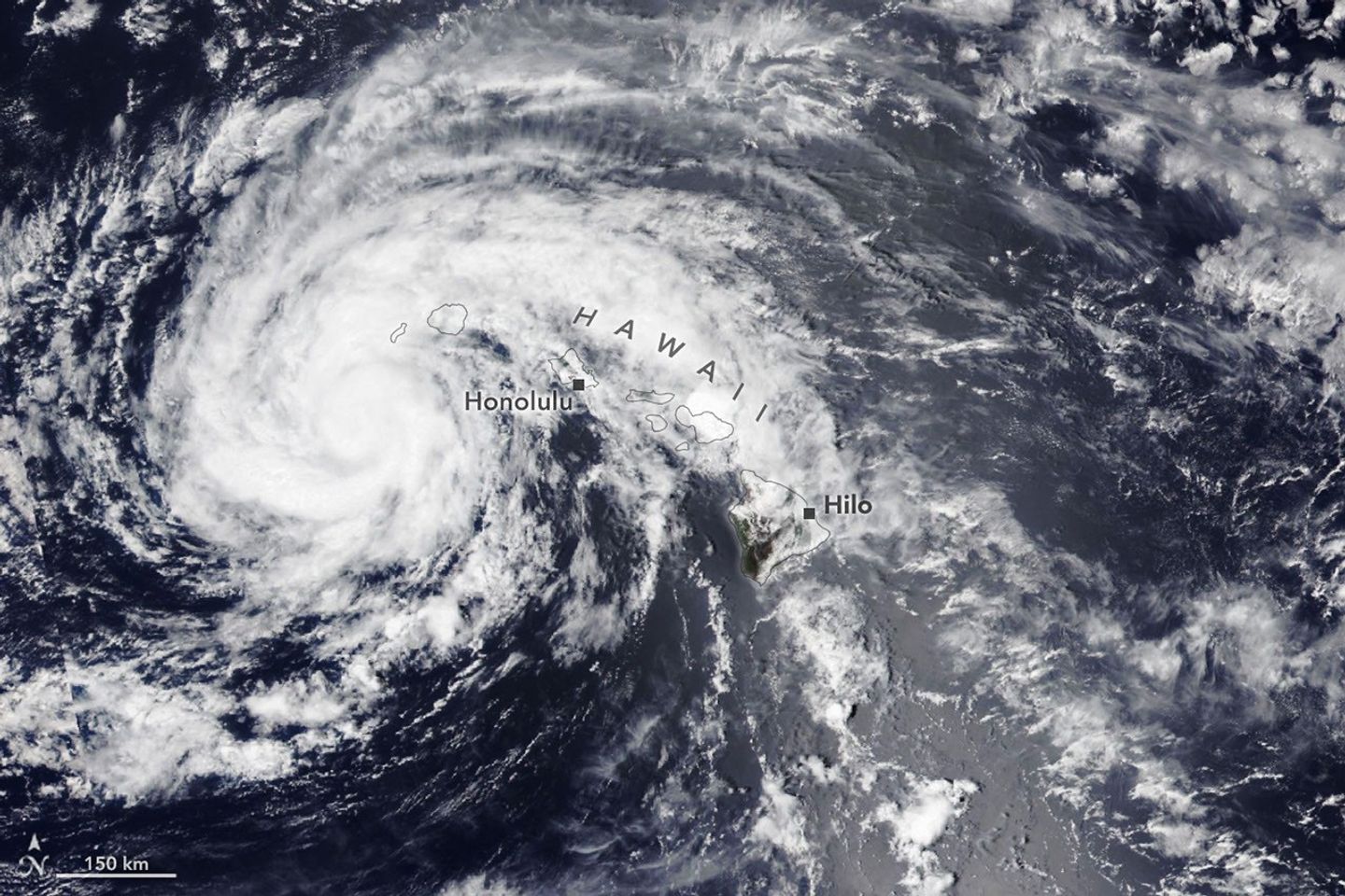
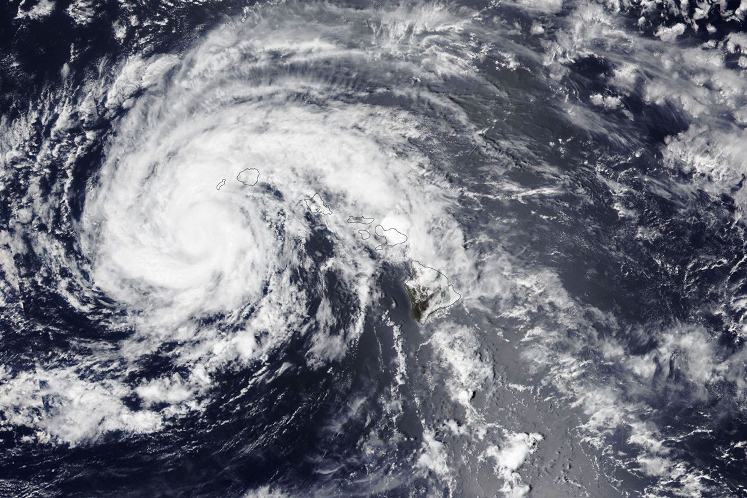
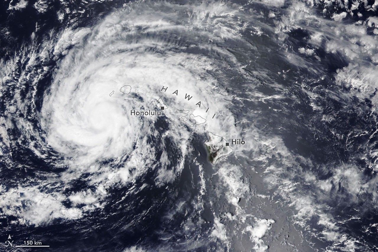
The spiraling clouds of a tropical storm are centered near the Hawaiian island of Kauaʻi.
NASA Earth Observatory / Lauren Dauphin

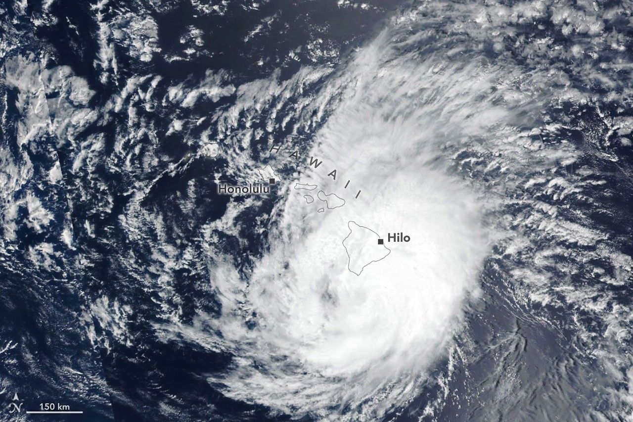
The spiraling clouds of a hurricane appear near the Hawaiian Islands. Its eye is just south of the Island of Hawaiʻi.
NASA Earth Observatory / Lauren Dauphin

The spiraling clouds of a tropical storm are centered near the Hawaiian island of Kauaʻi.
NASA Earth Observatory / Lauren Dauphin

The spiraling clouds of a hurricane appear near the Hawaiian Islands. Its eye is just south of the Island of Hawaiʻi.
NASA Earth Observatory / Lauren Dauphin


August 16, 2026

August 15, 2026


Lala skirts south of the Island of Hawaiʻi as a category 1 hurricane in the right image, acquired by the VIIRS (Visible Infrared Imaging Radiometer Suite) on the Suomi NPP satellite on August 15, 2026, at about 1:45 p.m. Hawaii Standard Time (23:45 Universal Time). The storm decreased in intensity while tracking northwest and was a tropical storm when the VIIRS on the NOAA-20 satellite captured the left image about 24 hours later. NASA Earth Observatory images by Lauren Dauphin.

The Island of Hawaiʻi narrowly avoided a direct landfall by Hurricane Lala in mid-August 2026. The storm nonetheless delivered serious damage as it passed just south of the island on August 15 (above, right) as a category 1 storm on the Saffir-Simpson wind scale.

Lala brought rainfall totals exceeding 20 inches (50 centimeters) to parts of the island, causing flash flooding and ongoing mudflow risks. The highest rainfall total for the storm—43.55 inches (110.6 centimeters) as of the morning of August 17—was recorded at Laupāhoehoe, on the coast northwest of Hilo. Lala downed trees, damaged bridges, and knocked homes off their foundations. Coastal areas were pummeled by large waves, while the summit of Mauna Kea, over 13,000 feet (4,000 meters) above sea level, experienced blizzard conditions.

By early afternoon on August 16, when the other image (left) was acquired, the storm had tracked northwest, roughly parallel to the island chain, and was southwest of Kauaʻi. Lala had decreased in intensity to a tropical storm, with sustained winds of 65 miles (105 kilometers) per hour, according to the National Hurricane Center.

While the Island of Hawaiʻi took the brunt of the storm, other islands also saw destructive effects. Strong winds caused widespread power outages, with more than 220,000 customers statewide without power as of the afternoon of August 16, according to news reports. Across the islands, wind and rain damaged infrastructure, and floodwaters and debris rendered roads impassable.

It has been an active tropical cyclone season in the Eastern Pacific so far in 2026, meteorologists note, consistent with what scientists expect during an El Niño, which has been underway as of mid-June. Warm water in the equatorial Pacific—the hallmark of El Niño—and the moisture and energy it transfers to the atmosphere help fuel nascent tropical storms. Lack of wind shear, another typical El Niño pattern in this region, also encourages tropical storms to develop and strengthen. The Atlantic hurricane season, in contrast, has been relatively calm, as greater wind shear over the Atlantic Ocean and Caribbean Sea during an El Niño inhibits hurricane formation by dissipating the upward motion of heat.

NASA Earth Observatory images by Lauren Dauphin, using VIIRS data from NASA EOSDIS LANCE, GIBS/Worldview, and the Joint Polar Satellite System (JPSS). Story by Lindsey Doermann.

References & Resources

You may also be interested in:

Stay up-to-date with the latest content from NASA as we explore the universe and discover more about our home planet.

Tropical Storm Arthur

2 min read

The first named storm of the 2026 Atlantic hurricane season brought intense rainfall and the threat of flash flooding to…

Article

Typhoon Jangmi

2 min read

The sprawling storm promised to deliver torrential rain across a wide swath of southern Japan.

Article

Super Typhoon Sinlaku

3 min read

The violent storm aimed at the U.S. Northern Mariana Islands and Guam in mid-April 2026.

Article

Source: science.nasa.gov

APOD: 2026 August 28 – The Sky Turns Above Paranal

APOD

Astronomy Picture of the Day

Discover the cosmos! Each day a different image or photograph of our fascinating universe is featured, along with a brief explanation written by a professional astronomer.

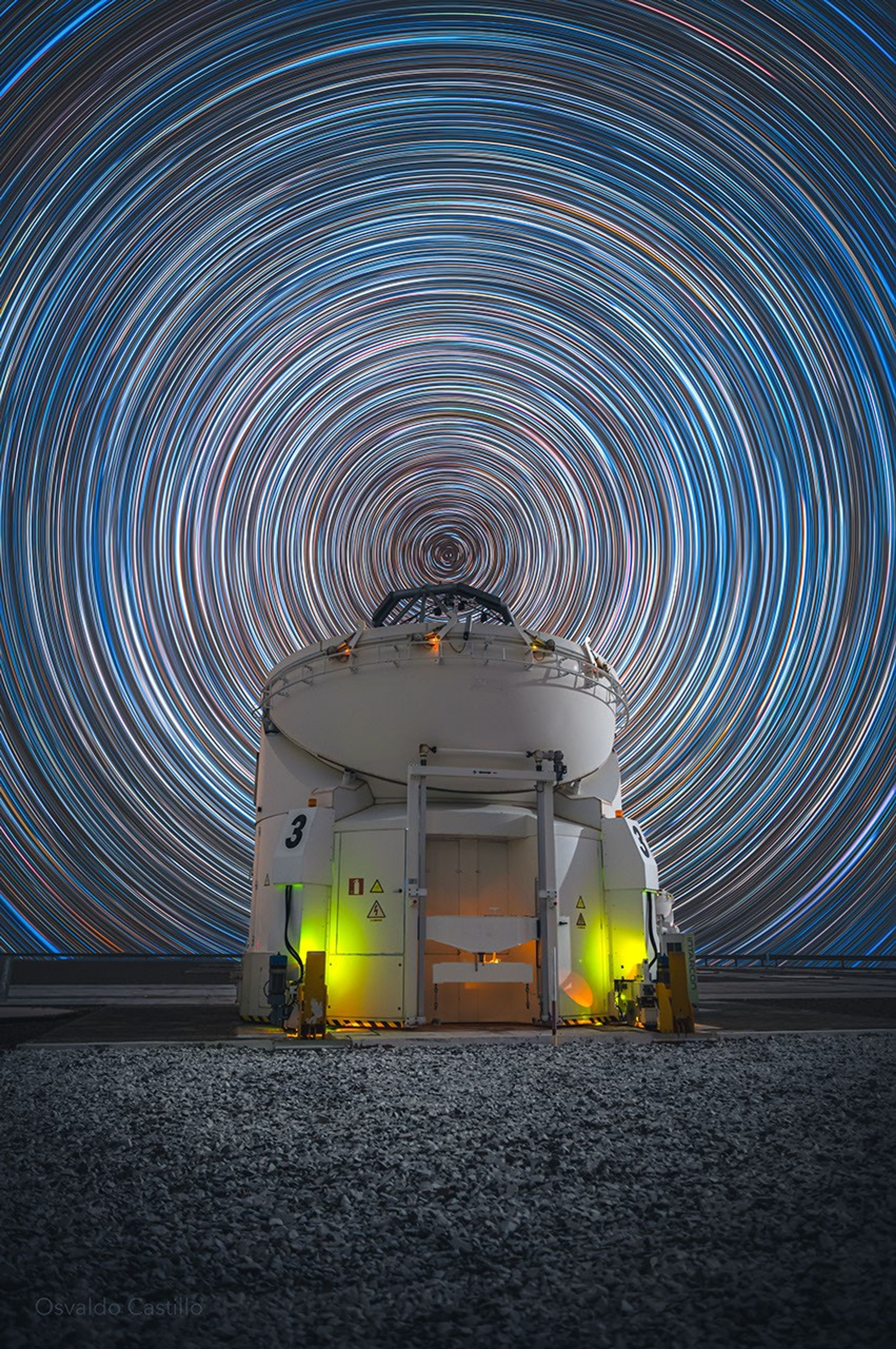
A picture of star trails in the night sky above a telescope.

The Sky Turns Above Paranal

Explanation: At the latitude of ESO’s Paranal Observatory in Chile, about 25 degrees south, Earth’s rotation moves the planet’s surface eastward at over 1,500 kilometers per hour. And while that’s faster than the speed of sound at sea level, the motion is imperceptible. Still, that motion can be revealed in the apparent rotation of the night sky by photographing star trails. This star trail image was composed from a digital stack of 300 consecutive 25-second exposures made with a camera fixed to a tripod to trace the star trail arcs. The graceful arcs are concentric and centered at the south celestial pole, the southern hemisphere extension of Earth’s axis of rotation into space. One of the observatory’s operating 1.8 meter auxiliary telescopes, AT 3, appears beneath the south celestial pole, faintly illuminated in the foreground of this well-planned scene from a rotating planet.

APOD’s main NASA site is moving: From apod.nasa.gov to science.nasa.gov/apod

Tomorrow’s picture: pixels in space

Date August 28, 2026
Credit & Copyright: Osvaldo Castillo
Authors & editors: Jerry Bonnell, Cecilia Chirenti, Robert Nemiroff, Keighley Rockcliffe
A service of: ASD at NASA / GSFC,
NASA Science Activation & Michigan Tech. U.

Source: science.nasa.gov

Ribbon-Cutting Event for NASA Deep Space Network’s Deep Space Station 23

2 Min Read

Ribbon-Cutting Event for NASA Deep Space Network’s Deep Space Station 23

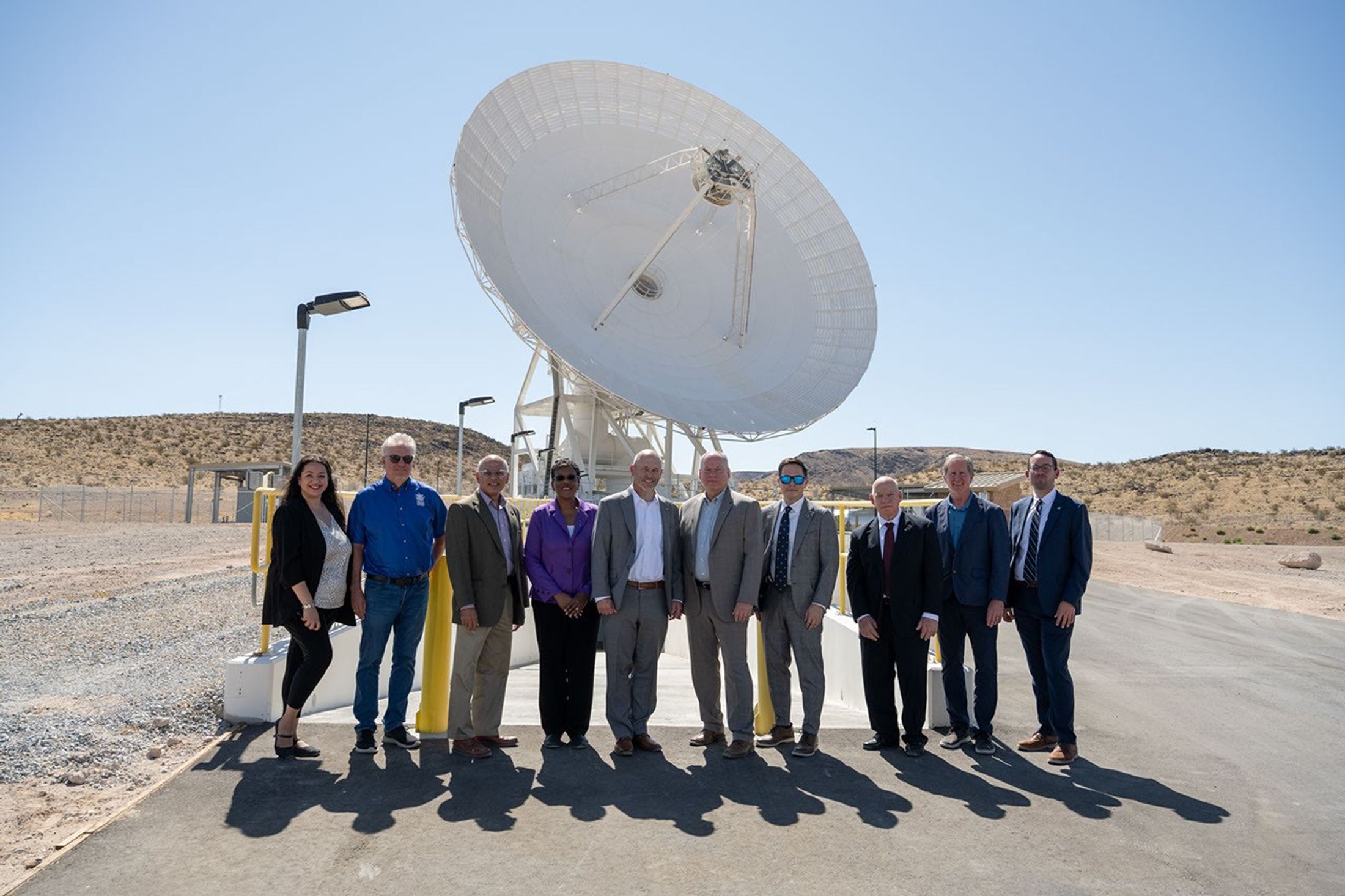
Ten people in professional attire pose together outside under a clear blue sky, with a massive white satellite dish standing directly behind them.

PIA26779

Credits:
NASA/JPL-Caltech

Description

Leadership from NASA Headquarters, the Jet Propulsion Laboratory, and the Deep Space Network (DSN) stand in front of the recently completed Deep Space Station 23 antenna at the Deep Space Network’s Goldstone complex near Barstow, California, on Aug. 25, 2026. 

From left: Germaine Aziz (project manager, DSN Aperture Enhancement Project, JPL); Bradford Arnold (manager, Telecom Programs & Oversight, JPL); Keyur Patel (associate lab director for Flight Projects & Mission Success, JPL); Wanda Peters (deputy associate administrator, Research and Technology Mission Directorate, NASA Headquarters); Jimmy Kenyon (associate administrator, RTMD, NASA Headquarters); John McCullough (acting director, Space Communications and Navigation Program, NASA Headquarters); Gregory Heckler (deputy program manager for capability development, SCaN, NASA Headquarters); William Marinelli (development manager, SCaN, NASA Headquarters), Michael Levesque (project manager, DSN, JPL); and Frank Kaufholod (project manager, NASA Glenn Research Center).

They gathered at the recently completed DSS-23 antenna for a ceremonial ribbon cutting on Aug. 25, 2026. It’s the latest antenna to be added as part of the DSN’s Aperture Enhancement Project, which began in 2009 to upgrade and expand the network by adding six new 34-meter (114-foot) multifrequency beam-waveguide antennas. These versatile Deep Space Network dishes can enhance many missions operating over different radio frequencies. 

The DSN allows missions to track, send commands to, and receive scientific data from faraway spacecraft. It is managed by JPL, a division of Caltech, in Southern California for SCaN, which is located at NASA Headquarters within RTMD.

For more information about the DSN, visit:

https://www.nasa.gov/communicating-with-missions/dsn/

Source: science.nasa.gov

NASA Deep Space Network’s New Goldstone Antenna Goes Online

1 Min Read

NASA Deep Space Network’s New Goldstone Antenna Goes Online

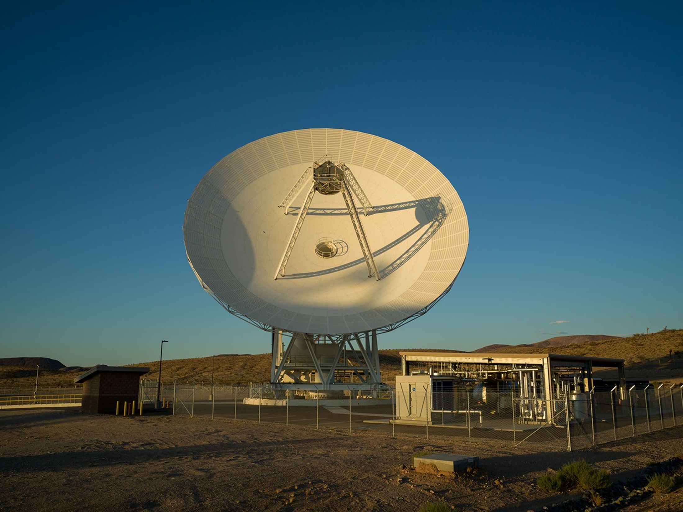
A massive white satellite dish antenna stands on a desert plain under a clear blue sky, bathed in warm sunlight alongside small facility structures.

PIA26778

Credits:
NASA/JPL-Caltech

Description

Long shadows are cast by the recently completed Deep Space Station 23 at the Deep Space Network’s Goldstone complex near Barstow, California, in August 2026. A 34-meter (114-foot) multifrequency beam-waveguide antenna, DSS-23 will boost the DSN’s capacity and enhance NASA’s deep space communications capabilities for decades to come.

NASA leadership and personnel as well as dignitaries gathered at the complete DSS-23 antenna for a ceremonial ribbon cutting on Aug. 25, 2026. It’s the latest antenna to be added as part of the Deep Space Network’s Aperture Enhancement Project, which began in 2009 to upgrade and expand the network by adding six new 34-meter multifrequency beam-waveguide antennas. These versatile Deep Space Network dishes can enhance many missions operating over different radio frequencies. 

The DSN allows missions to track, send commands to, and receive scientific data from faraway spacecraft. It is managed by NASA’s Jet Propulsion Laboratory, a division of Caltech, in Southern California for the agency’s Space Communications and Navigation (SCaN) Program, which is located at NASA Headquarters within the Research and Technology Mission Directorate.

For more information about the DSN, visit:

https://www.nasa.gov/communicating-with-missions/dsn/

Source: science.nasa.gov

Panorama Showcasing the 34-Meter Antennas of the DSN’s Goldstone Complex

2 Min Read

Panorama Showcasing the 34-Meter Antennas of the DSN’s Goldstone Complex

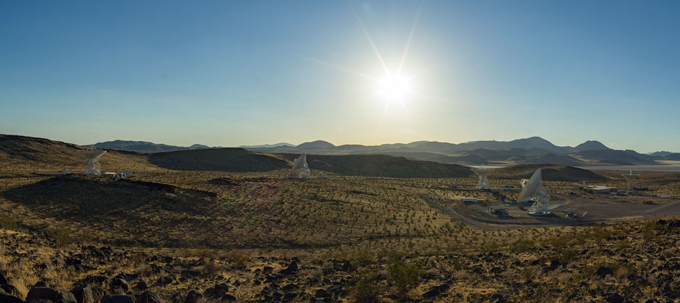
A wide desert landscape featuring several large white satellite dishes pointing toward a bright sun shining in a clear blue sky above distant mountain ranges.

PIA26777

Credits:
NASA/JPL-Caltech

Description

Five antennas soak in the summer sun at the Deep Space Network’s Goldstone complex near Barstow, California, in August 2026. The recently completed Deep Space Station 23, a 34-meter (114-foot) beam-waveguide antenna, can be seen to the right of the frame in the foreground. The other three 34-meter antennas are, from left, DSS-26, DSS-25, and DSS-24. At farthest right is a smaller 26-meter (85-foot) antenna, the retired “Apollo Antenna” that was built in 1967 as part of the Manned Space Flight Network and earned its nickname for providing tracking for the Apollo Program.

NASA leadership and personnel as well as dignitaries gathered at the complete DSS-23 antenna for a ceremonial ribbon-cutting on Aug. 25, 2026. It’s the latest antenna to be added as part of the Deep Space Network’s Aperture Enhancement Project, which began in 2009 to upgrade and expand the network by adding six new 34-meter multifrequency beam-waveguide antennas. These versatile Deep Space Network (DSN) dishes can enhance many missions operating over different radio frequencies. 

The DSN allows missions to track, send commands to, and receive scientific data from faraway spacecraft. It is managed by NASA’s Jet Propulsion Laboratory in Southern California, a division of Caltech, for the agency’s Space Communications and Navigation (SCaN) Program, which is located at NASA Headquarters within the Research and Technology Mission Directorate.

For more information about the DSN, visit:

https://www.nasa.gov/communicating-with-missions/dsn/

Source: science.nasa.gov

NASA’s Dark Universe-Seeking Nancy Grace Roman Space Telescope Launches

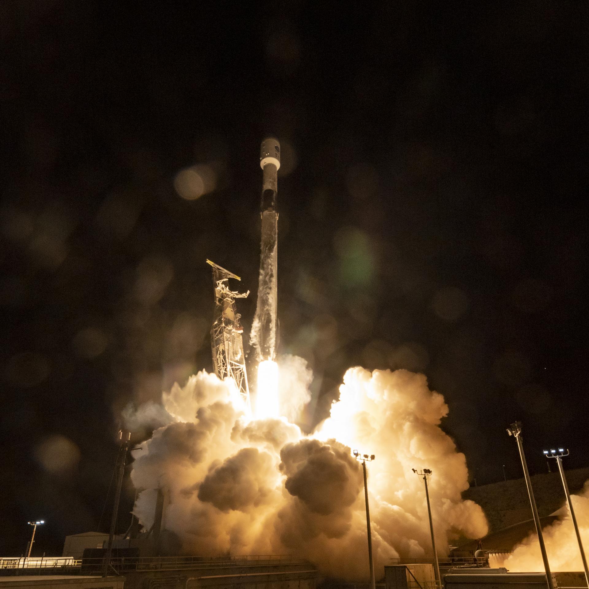
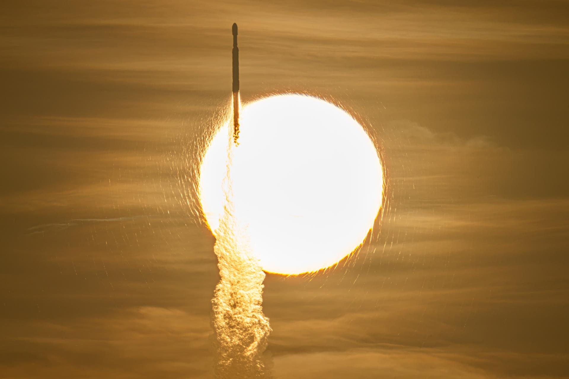
A SpaceX Falcon Heavy rocket with NASA’s Nancy Grace Roman Telescope on board is seen transiting the sun during launch from Launch Complex 39A, Sunday, Aug. 30, 2026, at NASA’s Kennedy Space Center in Florida.
NASA/John Kraus

Now on a three-month, million-mile journey to its final orbit, NASA’s Nancy Grace Roman Space Telescope will soon reveal the universe’s darkest secrets. The mission launched at 7:26 a.m. EDT Sunday aboard a SpaceX Falcon Heavy rocket from Launch Complex 39A at the agency’s Kennedy Space Center in Florida.

Roman pairs a large field of view with crisp infrared vision to explore vast swaths of the sky and probe deeply into cosmic history. This flagship mission will help astronomers explore dark matter, dark energy, and worlds outside of our solar system, known as exoplanets. Its surveys will support a broad range of research extending far beyond the mission’s main science goals.

“Roman is exactly the kind of success story we want to see across NASA,” said NASA Administrator Jared Isaacman. “Delivered ahead of schedule and on budget, this mission reflects more than a decade of dedication from the NASA workforce and our industry partners. Now, Roman will give us a new atlas of the universe, push the boundaries of discovery, and demonstrate what is possible when America’s space program pairs bold ambition with disciplined execution.”

The ground control team at NASA’s Goddard Space Flight Center in Greenbelt, Maryland, began receiving telemetry data from Roman seven minutes after launch. The Falcon Heavy rocket performed as expected, separating from the observatory 31 minutes into the flight. After separating from the center core, the rocket’s boosters safely returned to the launch site for refurbishment.

“Roman will be a discovery machine that will bring us closer than ever before to answering humanity’s most profound questions about our cosmic history,” said Nicky Fox, associate administrator for the Science Mission Directorate at NASA Headquarters in Washington. “With its large field of view and fast survey speeds, Roman will usher us into a new era of discovery and make the invisible visible, setting the foundation for humanity’s search for life beyond our solar system.”

During launch and early orbit, Roman uses the Near Space Network’s ground stations and relay satellites to exchange tracking, telemetry, and command data with ground controllers. About 70 minutes after launch, the Deep Space Network takes over communications and guides Roman toward the second Sun-Earth Lagrange point, or L2, about one million miles from Earth. Roman connects to that network through the Canberra Deep Space Communication Complex in Australia first. Approximately six hours later it will transfer to the Madrid Deep Space Communication Complex in Spain and then to the Goldstone Deep Space Communication Complex in California, ensuring continuous contact with Roman throughout its journey.

The Roman team also confirmed successful deployment of the observatory’s solar panels and lower instrument sun shade an hour and 23 minutes after launch. Within the upcoming days, Roman’s high-gain antenna and visor-like deployable aperture cover will deploy, ground controllers will initiate the first of two-mid-course corrections, and the Coronagraph Instrument will power on. This instrument will demonstrate the technology that future missions like NASA’s Habitable Worlds Observatory concept could use to image Earth-like planets in the search for life in the universe. Roman’s Coronagraph will take a giant step in that direction by snapping pictures of Jupiter-like planets.

A few weeks into Roman’s voyage, its primary instrument, the Wide Field Instrument, will activate. This 300-megapixel infrared camera has 18 4K detectors, each about the size of a saltine cracker. These detectors collect photons of light that will be decoded into crisp cosmic panoramas. Thanks to the observatory’s rigid design and stable optical performance, it will rapidly scan the sky without needing substantial time between separate observations. The Roman telescope is designed to survey the universe a thousand times faster than NASA’s Hubble Space Telescope.

Throughout the rest of Roman’s three-month commissioning period, scientists will run the instruments through a series of calibrations and tests. NASA anticipates releasing Roman’s first images by early 2027.

Roman will send back 1.4 terabytes of data every day, the highest data rate of any NASA astrophysics mission, so far. Machine learning, artificial intelligence, and citizen scientists will help sift through it and flag significant findings, which astronomers can then study.

“We’ve never been able to view the universe with eyes like Roman’s before,” said Julie McEnery, Roman’s senior project scientist at NASA Goddard. “There’s no telling what more we’ll know and have seen by this time next year.”

Roman is the fourth primary mission NASA has launched on a Falcon Heavy rocket. Earlier this year, the agency’s Launch Services Program worked with SpaceX to accelerate the launch date to accommodate the space telescope’s early completion.

The telescope is managed at NASA Goddard with participation by the agency’s Jet Propulsion Laboratory in Southern California; Caltech/IPAC in Pasadena, California; the Space Telescope Science Institute in Baltimore; and a team of scientists from various research institutions. The primary industrial partners are BAE Systems Inc., L3Harris Technologies, and Teledyne Scientific & Imaging. Contributions to Roman also are made by ESA, JAXA, the French space agency CNES (Centre National d’Études Spatiales), and the Max Planck Institute for Astronomy in Germany.

To learn more about the Roman mission, visit:

https://www.nasa.gov/roman

-end-

George Alderman / Alise Fisher
Headquarters, Washington
202-358-1600
[email protected] / [email protected]

Claire Andreoli
Goddard Space Flight Center, Greenbelt, Md.
202-286-1940
[email protected]

Source: www.nasa.gov

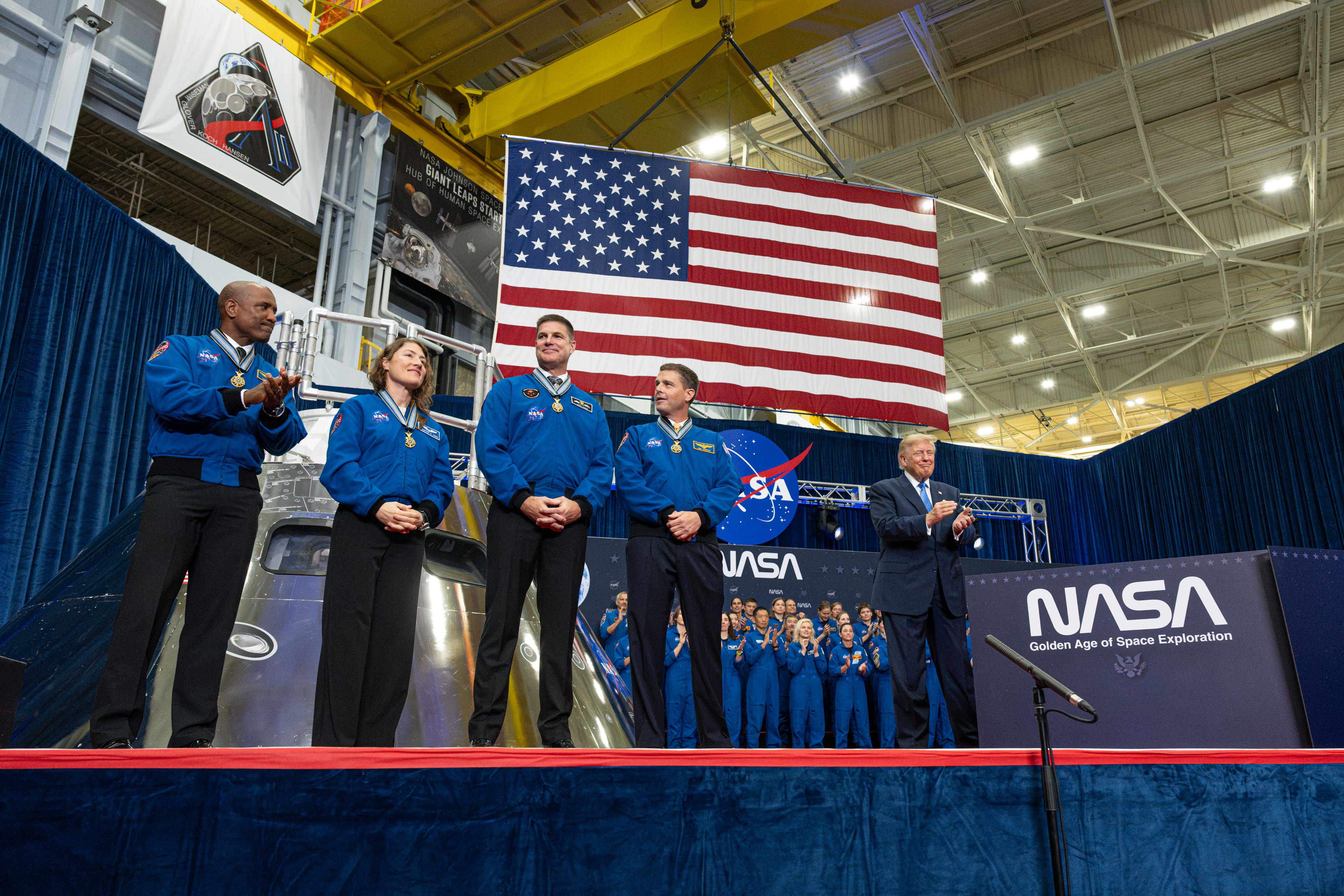
NASA’s Artemis II Crew Receives Congressional Space Medal of Honor

The four members of the Artemis II mission stand on stage after receiving the Congressional Space Medal of Honor. To their right is President Trump.
President Donald J. Trump awarded NASA astronauts Victor Glover and Christina Koch, CSA (Canadian Space Agency) astronaut Jeremy Hansen, and NASA astronaut Reid Wiseman with the Congressional Space Medal of Honor on Aug. 28, 2026, at NASA’s Johnson Space Center in Houston.
NASA/John Kraus

From left to right: NASA astronauts Victor Glover and Christina Koch, CSA (Canadian Space Agency) astronaut Jeremy Hansen, and NASA astronaut Reid Wiseman receive the Congressional Space Medal of Honor from President Donald J. Trump on Aug. 28, 2026, for their service during the Artemis II mission.

The Congressional Space Medal of Honor was authorized by Congress in 1969 to recognize an astronaut who in the performance of duties has distinguished himself or herself by exceptionally brave and meritorious efforts, and contributions to the welfare of the nation and humanity. There now are 34 recipients of the award since the beginning of the space program, including the crews of Apollo 1, Challenger, and Columbia who received the award posthumously.

Image credit: NASA/John Kraus

Source: www.nasa.gov
NASA Awards First Prize in Phase 2 of Agency’s LunaRecycle Challenge 

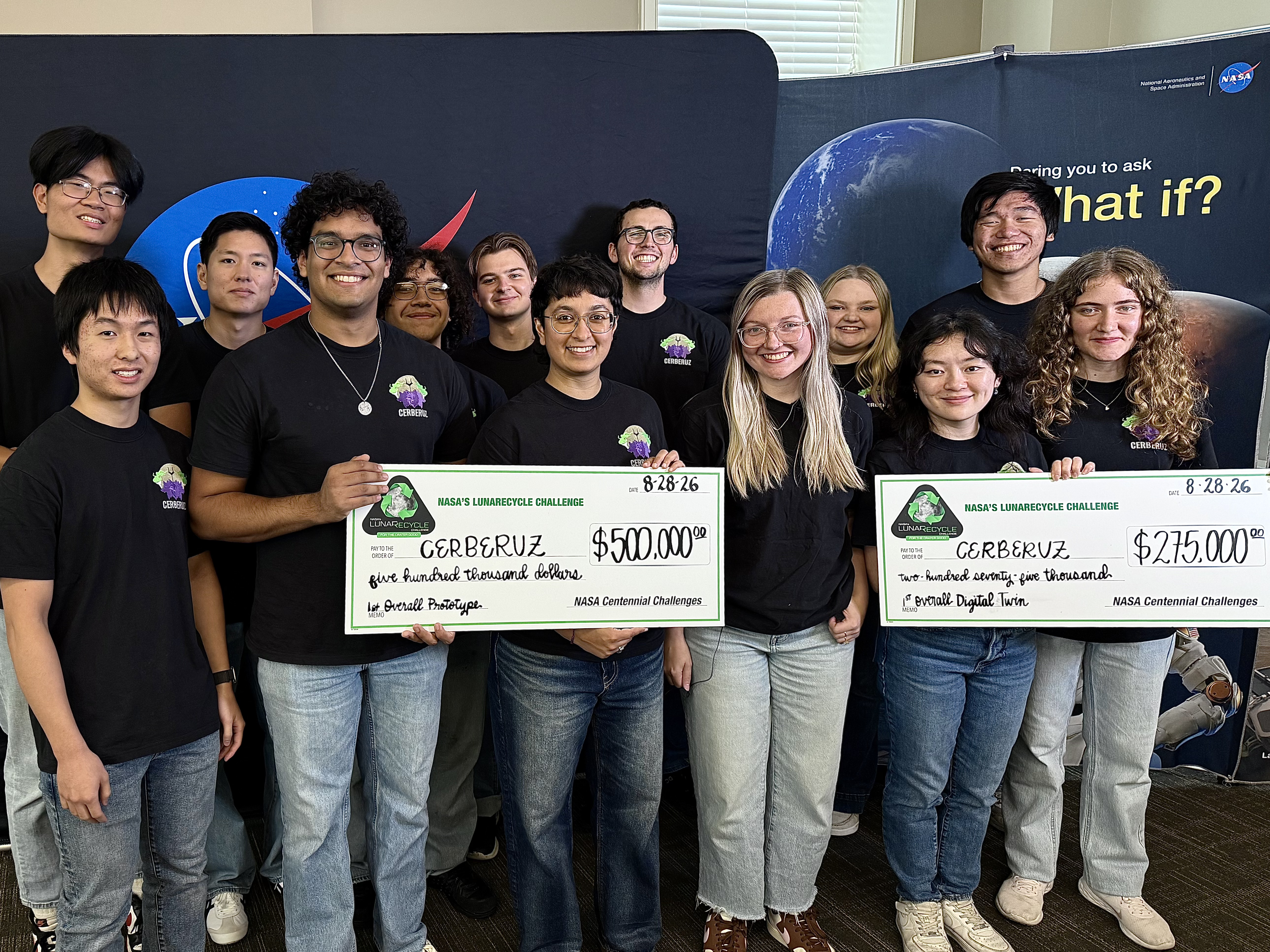
The Massachusetts Institute of Technology team won NASA’s LunaRecycle Challenge competition for their project, Composites for Extraterrestrial Recycling By Engineering the Reuse and Upcycling of Zotek (CERBERUZ).
Credit: NASA/Savannah Bullard

NASA named a team from the Massachusetts Institute of Technology (MIT) as the first prize winner for Phase 2 of the agency’s LunaRecycle Challenge, which focused on developing solutions for reducing waste during missions to the Moon or deep space by recycling common materials, like fabrics, plastics, foam, and metals. 

The Composites for Extraterrestrial Recycling By Engineering the Reuse and Upcycling of Zotek (CERBERUZ) team, comprised of undergraduate, graduate, and doctoral students at MIT, received a total of $775,000 in awards.  

The technology grinds mixed trash into a fine powder, repurposing materials such as Zotek foam as reinforcement rather than treating it as contamination that needs to be sorted out. The powder becomes feed for use as injection-mold finished parts or 3D-printing filament. The MIT team won in both the competition’s prototype development track and in the track focused on developing virtual models, known as “digital twins,” of recycling systems. 

“The LunaRecycle Challenge finale is the culmination of two years of innovation spurred by this competition,” said Jennifer Edmunson, program manager for Centennial Challenges at NASA’s Marshall Space Flight Center in Huntsville, Alabama. “It’s incredible to see these technologies go from concept to prototype and digital twin demonstrations in that time. Driving rapid and creative innovation is what NASA challenges are all about.” 

LunaRecycle is a $3 million, two-phase competition in partnership with The University of Alabama Lee J. Styslinger Jr. College of Engineering. Phase 2 of the competition required U.S. teams to submit a prototype, with an optional digital twin serving as a virtual model of it.

For Phase 2, 14 finalist teams from across the United States gathered at The University of Alabama’s Lee J. Styslinger Jr. College of Engineering, in Tuscaloosa, from Aug. 24 to Aug. 28 to demonstrate their technology prototypes. The digital twin models submitted by some teams were also presented alongside their respective prototypes.

The competitors’ backgrounds ranged from university students and faculty to entrepreneurs and space technology enthusiasts. Teams were encouraged to envision solutions that not only addressed recycling in deep space, but that also could have applications on Earth. 

Along with the first prize winner, nine teams received prizes: 

Prototype track winners: 

  • Second place overall ($225,000): Terasynth from Orlando, Fla. with Lunar Re-Forge System 
  • Most Innovative ($50,000): RECLAIM from Penn State University with the Resource Extraction and Conversion from Lunar Anthropogenic Inputs with Microwaves (RECLAIM) system 
  • Highest Mass Efficiency ($50,000): Cislune from Rosemead, Calif. with the Carbon Recovery and Feedstock Transformation for Extraterrestrial Reuse (CRAFTER) system 
  • Most Trash Types Recycled ($50,000): Team Lovegrove from Bob Jones University in Greenville, S.C. with LunaBrix 

Additional digital twin track winners: 

  • Second place overall ($125,000): Moon Made from Boulder, Co. with Fiber Forge 
  • Most Innovative ($25,000): RECLAIM from Penn State University with the RECLAIM system 
  • Best Visualization ($25,000): Waste Parrot Technologies from New York, N.Y. 

People’s choice winner ($25,000): 

  • Terasynth from Orlando, Fla. with Lunar Re-Forge System 

“This competition highlights how collaborations can lead to incredible solutions,” said Chris Frangione, who manages the LunaRecycle Challenge in support of NASA Centennial Challenges contracted through Amentum Space Exploration Division. “Between the solver teams, The University of Alabama, and NASA, this finale showcases what can be achieved when we bring together resources and great ideas towards a common goal.” 

The Phase 2 awards follow the success of the competition’s Phase 1, which received record-breaking interest from the global innovator community with more than 1,200 registrations – more than any competition in the 20-year history of NASA Centennial Challenges. For Phase 1, which concluded in 2025, participants from around the world could submit designs in either or both of the prototype or digital twin tracks. A panel of 50 judges evaluated nearly 200 Phase 1 submissions, selecting 17 teams representing five countries and nine U.S. states as winners.  Phase 2 entries were required to be unrelated to Phase 1. 

The LunaRecycle Challenge is managed at NASA’s Marshall Space Flight Center by Centennial Challenges, part of the Prizes, Challenges, and Crowdsourcing program within NASA’s Research and Technology Mission Directorate. NASA’s Centennial Challenges have a legacy of more than 20 years engaging the public to solve complex problems that benefit NASA’s broader initiatives. Past challenges have spurred advances in robotics, additive manufacturing, power and energy, textiles, chemistry, and biology. 

LunaRecycle is also supported by subject matter experts at NASA’s Kennedy Space Center in Florida, NASA’s Ames Research Center in California’s Silicon Valley, and NASA’s Langley Research Center, in Hampton, Virginia.  

To learn more about LunaRecycle, visit: 

www.nasa.gov/lunarecycle

Source: www.nasa.gov
NASA Johnson Pilots Chase Moon’s Shadow for Eclipse Science 

3 Min Read

NASA Johnson Pilots Chase Moon’s Shadow for Eclipse Science 

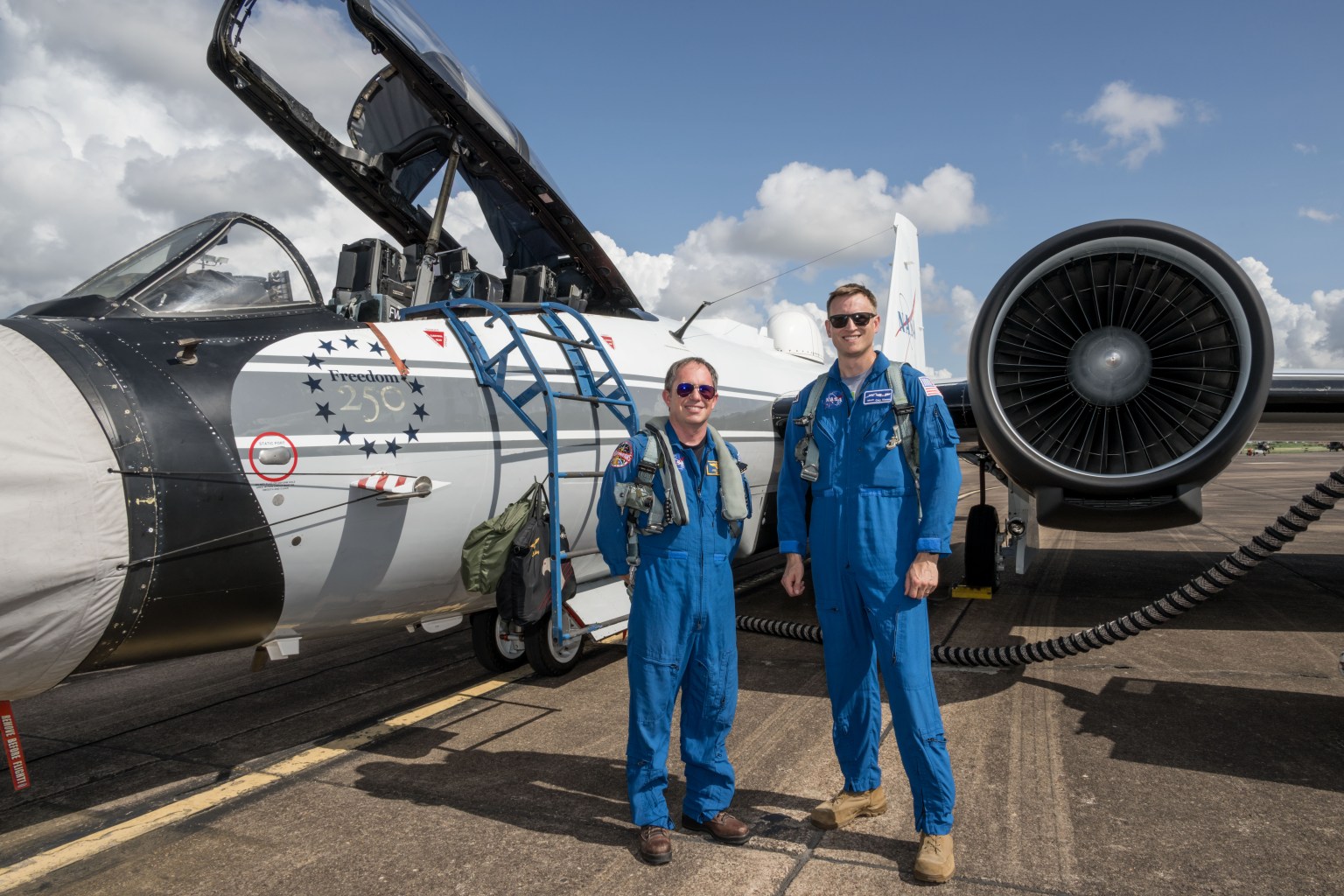
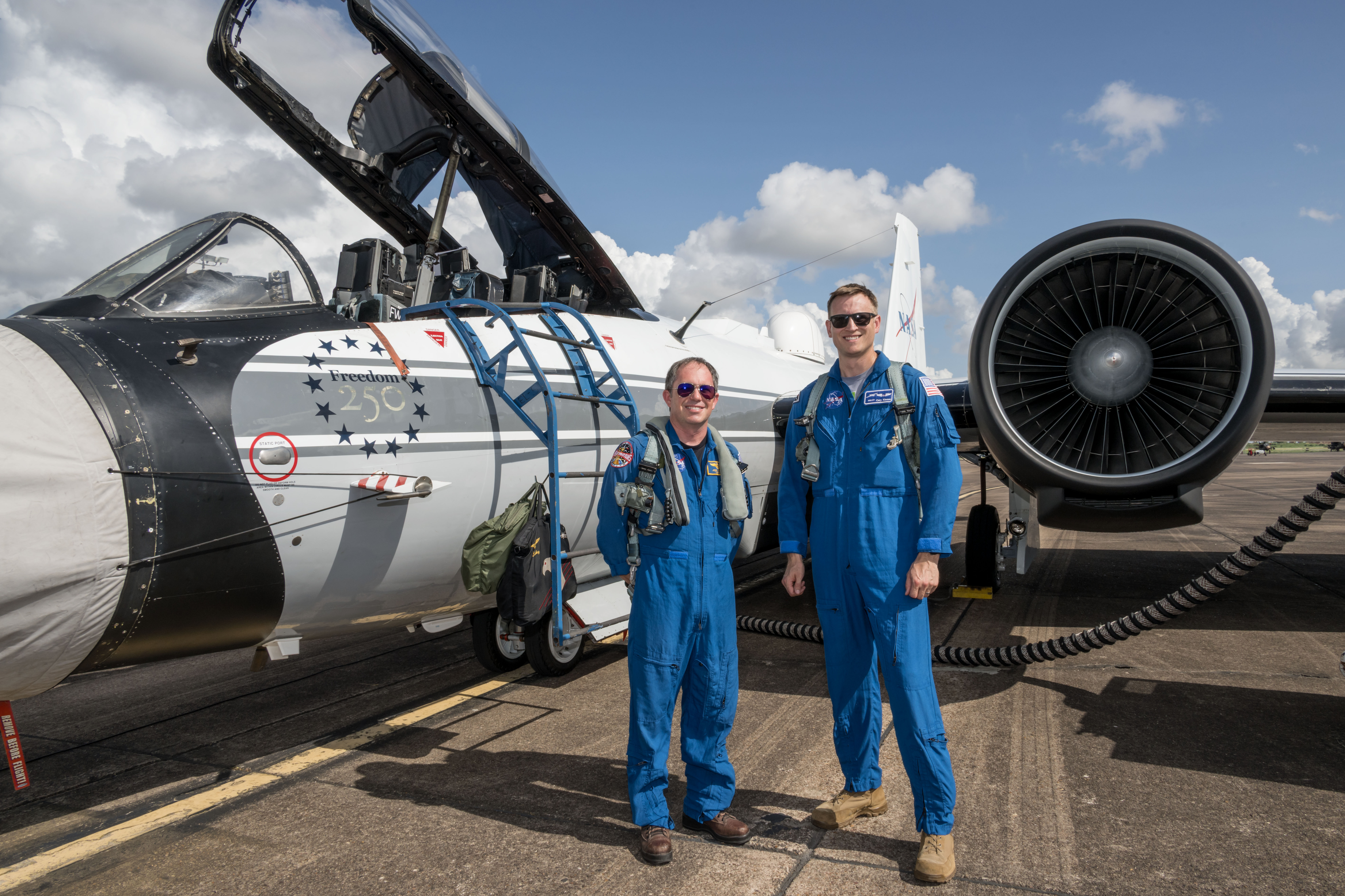
NASA’s WB-57F aircraft prepares for takeoff from Ellington Field in Houston ahead of its mission to observe the Aug. 12, 2026, total solar eclipse from Iceland. From left are John Gustine, NASA WB-57F pilot, and Cary Klemm, sensor equipment operator for NASA’s WB-57F.
NASA/Robert Markowitz

During the Aug. 12 total solar eclipse over Europe, scientists aimed to study a long-standing mystery: why the Sun’s outer atmosphere, the corona, is far hotter than its visible surface. Capturing the data they needed meant being in exactly the right place at the right time. 

Pilots from NASA’s Johnson Space Center flew the WB-57F high altitude research aircraft from Ellington Field in Houston to Iceland, their base for flying through the path of totality to give scientists a clearer view of the Sun’s corona. 

A total solar eclipse provides a unique opportunity to examine the corona because the Moon temporarily blocks the Sun’s bright surface, revealing its fainter outer atmosphere. Observations collected during this brief window can help scientists better understand how energy and material move through the corona and away from the Sun, improving our understanding of space weather. 

John Gustine, NASA WB-57F pilot, prepares for flight at Ellington Field in Houston ahead of the aircraft’s departure for Iceland to support the Aug. 12 total solar eclipse.
NASA/Robert Markowitz

At about 50,000 feet, the WB-57F flew above most clouds, dust, and water vapor that can interfere with observations from the ground. The altitude reduced atmospheric interference while also allowing the science instruments to observe infrared wavelengths that are largely absorbed lower in Earth’s atmosphere. 

Capturing those observations required careful coordination between scientists and the flight crew. Before the mission, teams calculated where the aircraft needed to be as the Moon’s shadow moved across the North Atlantic.  

“Going into a mission like this takes a huge team. It starts with the science team establishing the requirements, and then we work closely with them for months leading up to the mission,” said Tom Parent, NASA WB-57F pilot. “We rely heavily on our maintenance team to get the instruments serviced, prepared, loaded onto the aircraft, and flight tested. It’s a huge team effort to get an aircraft like this up there to image and achieve these objectives.” 

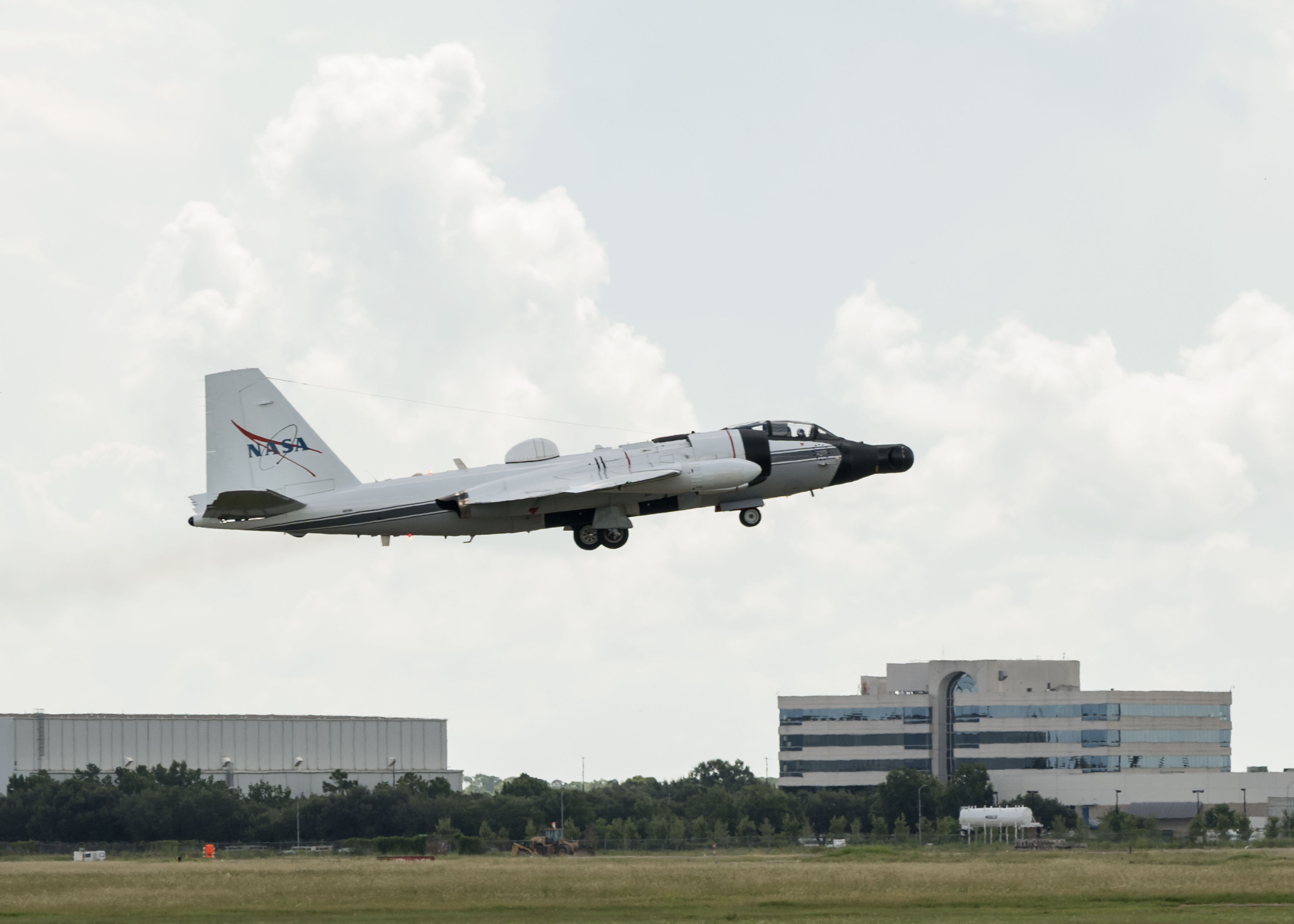
NASA’s WB-57F aircraft takes off from Ellington Field in Houston ahead of its mission supporting the Aug. 12 total solar eclipse from Iceland.
NASA/Robert Markowitz

During totality, NASA WB-57F pilot John Gustine positioned the aircraft along the eclipse path to maximize time in the Moon’s shadow and give scientists as much opportunity as possible to collect data. 

From the back seat, Cary Klemm, sensor equipment operator for NASA’s WB-57F, controlled the camera systems, adjusting focus and exposure times while tracking features of interest throughout totality. 

With the cameras capturing observations throughout the brief window, every second mattered. 

“Every image is another piece of data that could reveal something new about the Sun,” Klemm said. 

What scientists can learn from those observations reaches far beyond the eclipse itself. The Sun’s corona is made of plasma shaped by magnetic fields, and many of the same physical processes occur elsewhere in the universe. 

“The NASA WB-57F’s unique capabilities of high-altitude flight were truly crucial in providing access to these valuable wavelengths during an eclipse whose path crossed mostly over the ocean in an area where clouds are common,” said Amir Caspi, principal investigator for the study at Southwest Research Institute in Boulder, Colorado. “We could not have achieved this success without this platform, and all of the efforts of the many intrepid ground, air, and science crew members.”

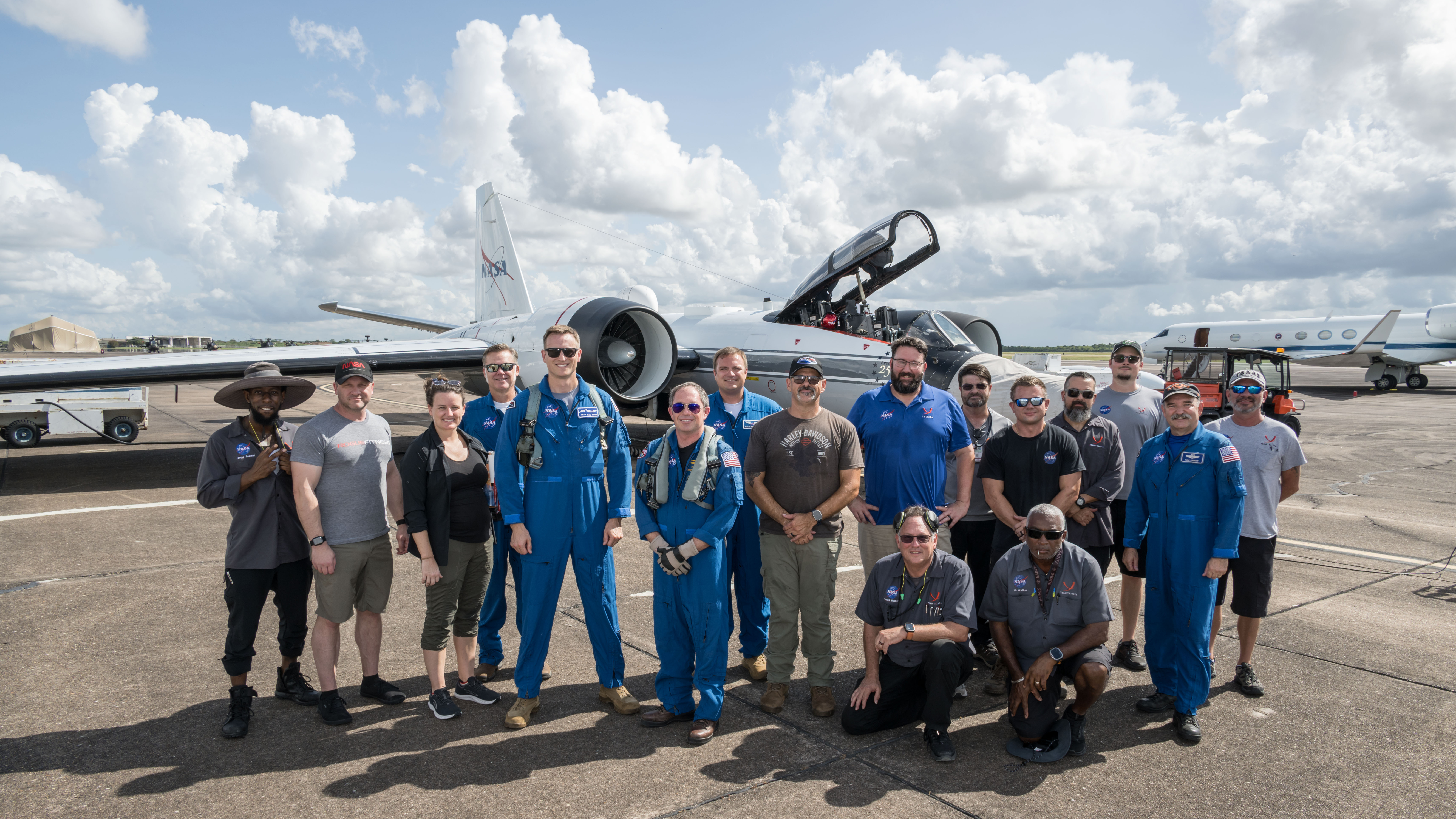
Members of NASA’s WB-57F eclipse mission team gather at Ellington Field in Houston ahead of the aircraft’s departure for Iceland.
NASA/Robert Markowitz

The data gathered during the flight will give scientists another opportunity to investigate the Sun and the processes that influence the space environment around Earth. 

View images and videos from NASA’s eclipse mission. 

About the Author

Sumer Loggins

Sumer Loggins

Source: www.nasa.gov